When it comes to CAN FD capabilities, it is surprisingly rare to find single-board computers (SBCs) that support it natively. In most cases, developers are forced to rely on external HATs or Shields. Fortunately, the BeagleBone AI is a rare exception, featuring a built-in CAN FD controller integrated directly into its TI AM67 SoC.
However, this controller is not enabled by default. To unlock native CAN FD support, you’ll need to perform a bit of manual configuration. This guide will walk you through the process.
Step 1: First, you need the Device Tree file that disables the CSI peripheral to make room for CAN FD. Note that on the BeagleBone AI, the CAN FD signals share pins with the CSI0 connector, meaning you can only use one of these features at a time.
Inside the repository, you will find:
.dtso: The human-readable source file..dtbo: The compiled binary overlay file.
If you don’t plan on modifying the code, you only need the .dtbo file.
Step 2: Copy the .dtbo file into your BeagleBone’s firmware overlays directory:
/boot/firmware/overlays/Step 3: Next, we need to instruct the bootloader to load the CAN FD overlay on startup. Open the configuration file and add the overlay path to the bottom of the file (typically around line #2 of the configuration block).
sudo nano /boot/firmware/extlinux/extlinux.conf
# Add this line
fdtoverlays /overlays/can1.dtbo 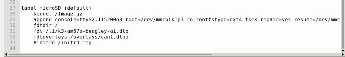
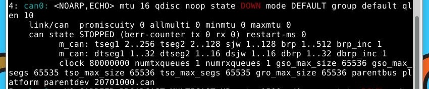
Step 3: Reboot your BeagleBoneY AI to apply the changes. Once booted up, run the following command to see your can0 come to life!
ip -d link show